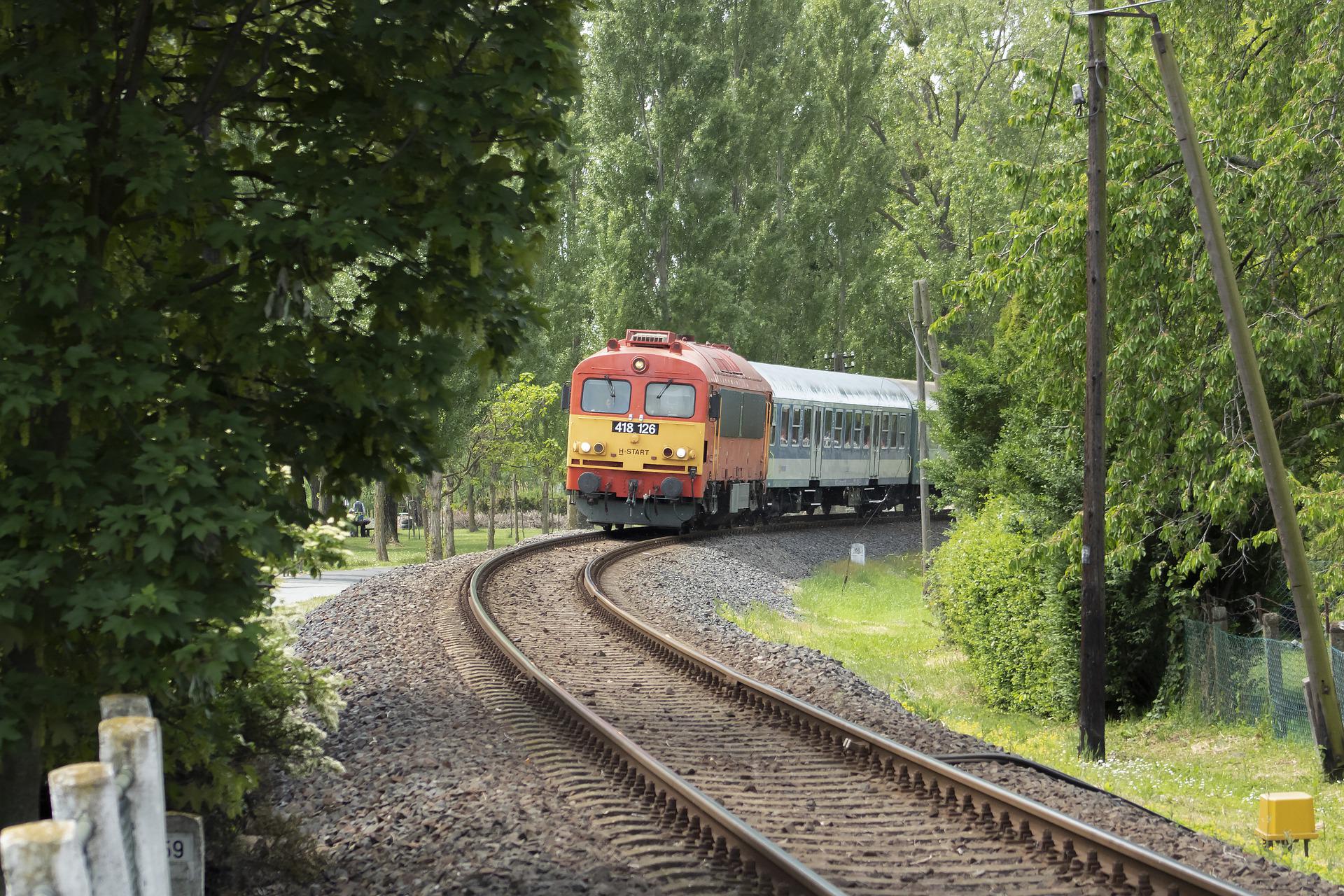
Most of applications of Robotran since its creation until today concern vehicles and more particularly railway vehicles. This article gives you a brief overview of different projects realized by the Robotran team. Links send you to more dedicated pages.
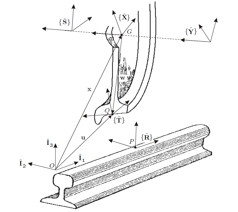
In the case of railway vehicles, an arduous aspect of the modelling phase results from the contact between the wheels and the track. Indeed, from a purely geometrical point of view, locating the contact between a wheel and a rail becomes complicated since both are profiled. Furthermore, from a dynamical point of view, the large number of parameters (shape of the profiles in contact, contact pressure, relative contact velocity, physical properties of the materials,…) leads to complex theories such as those developed by Prof. J.J. Kalker from T.U. Delft.
The classical approach for the geometrical problem is dedicated to conventional railway vehicles whose rolling elements consist of rigid wheelsets. The contact between a wheelset and a track has been abundantly developed in the literature. The corresponding models take advantage of the fact that the left and right wheels are rigidly linked by a common axle and have, generally, identical profiles.

When dealing with independent wheel, it is clear that each wheel/rail contact must be analyzed separately. An isolated wheel moving along on a straight track has five d.o.f. which could be naturally described by the lateral and longitudinal displacements of the wheel center of mass G, the yaw and roll angles of the wheel, and the rotation angle of the wheel around its axis of symmetry. This set of coordinates however requires solving a preliminary nonlinear geometrical problem, because the position of the wheel/rail contact point cannot be known in advance since the rail and the wheel are profiled (ex. S1002 wheel on UIC60 rail).
Using a general multibody approach, a geometrical and kinematic model of independent wheels on rail has been developed and implemented in ROBOTRAN to deal with any general configuration of bogies with independent wheels (tramways or high speed trains).
At UCLouvain, this model has been successfully used to analyze the behavior of high speed bogies or to check for the stability of tramways equipped with articulated bogies with independent wheels.
The application considered here is a subway bogie designed by Bombardier Transport for the city of Caracas (Venezuela). Unlike a classical bogie, this one has an articulated chassis separated into two longitudinal parts assembled by a central joint allowing for left/right relative pitch. Actually, this joint is made out of rubber and six relative degrees of freedom (d.o.f.) exist between the two parts of the chassis.
Two three-phase induction motors are coupled with the axles by means of reducers. These motors are supported by the chassis at two specific locations:
Subway bogies are commonly driven by DC-motors, but in this case, the motor manufacturer proposed to replace them by three phase inductive motors. The latter are characterized by important torque oscillations when starting and Bombardier’s engineers were worried about possible additional vibrations of the chassis, due to these torque oscillations. Indeed, additional vibrations could lead to fatigue issues, which should be avoided. The main objective in studying this bogie was thus to analyze the influence of the torque oscillations during starting of the bogie.
To achieve this goal, a strongly-coupled electro-multibody model was developed in Robotran using an original Lagrange formulation, involving both mechanical and electrical generalized coordinates.
Fortunately, after comparing the results with those obtained with classical DC-motors, we could not conclude for significant additional vibrations induced on the chassis of the bogie, when introducing three phase actuators.
A pedagocial demonstrator was developed on our lab to illustrate the wheel/rail guidance phenomenum of railway vehicles that is used for several decades. Check more on the dedicated page.