Bogie bench
What is a bogie?
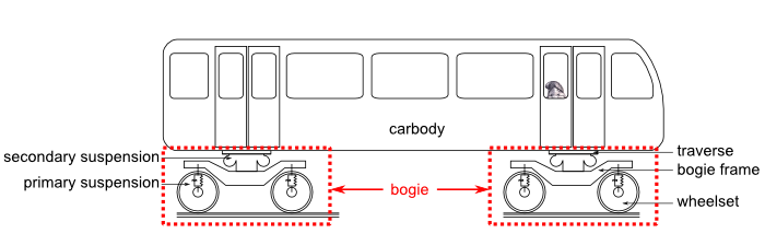
On a common train, metro or tram, the bogie ensures the link between the carbody and the track. Its main function is to ensure the vehicle guidance in safe conditions. It is commonly composed of a frame, two rigid wheelsets and two suspension stages: the primary suspension acting between the frame and the wheelset and the secondary suspension which essentially ensures the passenger comfort.
Realization
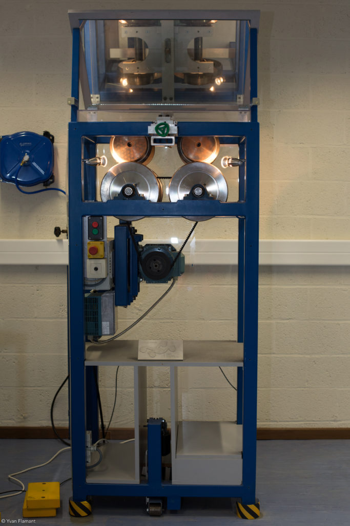
The test rig is illustrated in the opposite figure. A scaled bogie (around 1/5 scale), composed of an aluminum rigid frame and two wheelsets with conical running thread (rolling surface) laying on two roller pairs which replace the real track. The rollers are actuated by an electrical actuator that allows to impose different rotational speed to the bogie wheels.
The bench can illustrate, for a constant speed:
- the bogie centering submitted to a lateral initial displacement;
- the lateral stiffness of the bogie submitted to a constant lateral load;
- the lateral dynamic behavior of bogie:
- stable when running under a critical speed
- unstable when running above a limit speed
- possibly entering limit cycle between the two
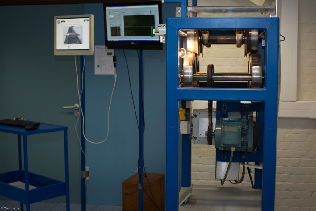
Lateral displacement and yaw angle are measured by sensors and displayed in real time on a screen next to the bench.

These experiments mainly demonstrate the « hunting motion » which combines lateral displacement and yaw angle (rotation along the vertical axis) of the bogie. This motion, stable for low speed, enters limit cycles when the speed is increased. This phenomenon originates from the forces occurring at the wheel/rail interface. These forces are quite complex and induces, from a mathematical point of view, high non-linearities in the equation of motion. For the highest speeds, the resulting instabilities engender large vibrations and harsh impact on the structure which focuses viewer attention, better that any simulation, on the potential dangerousness of the phenomenon.
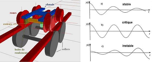
All these operations modes have also been simulated on a computer using a dynamic model implemented with dedicated software (multibody programs like Robotran developed at the CEREM, SIMPACK).
To strengthen the educational aspect of the bench, two devices were built.
The first one aims at accounting for the “lateral stiffness” that a bogie induces when rolling, thanks to the thread conicity: the visitor can pull itself the bogie in the lateral direction thanks to a handle and appreciate the large return force resulting from the wheel/rail contact.
The second one illustrates the behavior in a track curved and tilted: an electrical cylinder placed at the ground level tilts the whole structure with a 10° angle to “simulate” this situation. It can be observed that the bogie remains centered between the two rollers.
Moving illustrations
The following video illustrates the general functioning of the bench, with a view on the control screen on which the motion monitoring is displayed in real time. A mirror orientated at 45° is placed on the top of the view to visualize more easily the yaw motion. The bogie is placed at the eyes height to comfortably observe the wheel/rail contacts. The mechanisms are protected by a Plexiglas in order to avoid accident.
Bogie centering following a lateral disturbance
When the bogie is running at a speed lower than the so-called “critical speed”, it will automatically damp any lateral disturbance by doing its hunting motion. The following video demonstrates this phenomenon when the bogie is submitted to an initial lateral displacement. The typical screeching of the wheel on the rail clearly sounds and reminds the real bogie entering railway stations!
Limit cycle and derailment
Above a given velocity, the bogie loses its natural stability and the hunting motion is not damped anymore: it oscillates from left to right causing harmful, even dangerous, for the passengers. This phenomenon is illustrated here below.
For the highest speed, the oscillation amplitude increases endlessly, and the wheels hit the rail with their flange. This is illustrated below.
Conclusion and perspectives
A test rig has been built in order to highlight and characterize the kinematic and dynamic behavior of a railway bogie. It must be recalled that it has a strictly educational vocation and aims at demystifying the wheel/rail guidance phenomenon which relies on the small wheel conicity (1/20 or 1/40) and not on the flange contact as it can be guest from play activities (toys, miniature train, etc.)
This educational bogie is used as well as for mechanical courses at the Ecole Polytechnique de Louvain as for public demonstration, for instance in collaboration with the railway industry actors.