This project aims to design an active prosthesis for hip disarticulated amputee which respect the biomechanic of the user while also being compact enough. The resulting mechanism is a tilted double parallelogram and the actuator takes advantage of this parallelogram structure to optimize its transmission ratio.
Keywords: Prosthesis, Hip disarticulation, Amputee, Mechanism
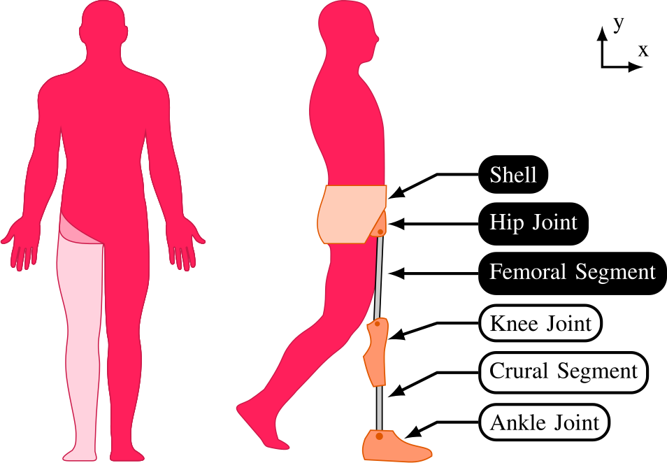
Hip Disarticulation and Hemipelvectomy (Figure 1, left) are the two most proximal amputation levels of the lower limb. Fortunately, these extremely mutilating interventions are not commonly performed.
Hip prostheses have been developed since the 70’s. The most frequently used device is called the “Canadian prosthesis” (Figure 1, right) and provides the replacement of the whole lower limb. The main component of a typical Canadian prosthesis are a shell, fitting to the stump and transmitting bodyweight to the prosthesis; the hip joint itself, that is locked during the stance phase and loose otherwise; and the femoral segment connected to the prosthetic knee module.
In the case of ankle and knee prostheses, there is a physical access to the joint center of motion. In contrast, for the hip, the center of motion is located in the pelvis, i.e., inside the shell, and is thus not physically accessible. To comply with the biomechanics of a sound hip, the center of motion of the prosthesis should coincide with its natural one. It is thus compulsory to implement a remote center of motion (RCM) in the mechanism.
A double parallelogram mechanism is a classical way to implement a fixed RCM. An implementation of this mechanism embodied as a hip prosthesis is provided in Figure 2. Point l, capturing the attachment point of the knee module, has to rotate around point o, capturing the hip natural center of motion. A classical straight double parallelogram (in green) can achieve this kinematics via a single attachment point a to the shell. The first parallelogram BCDE keeps ED parallel to BC. Point F extends segment ED such that the length EF is equal to the distance between o and B. Considering the virtual parallelogram oBEF, one can thus see that moving the first parallelogram makes F rotating along a circle of center o and radius BE. The second parallelogram EFGH guarantees that the femoral segment always stays oriented towards the remote center o. Point H lies in the prolongation of segment BE. Similarly as for F, point G rotates effectively around the center o. FG can thus be extended until point l where the knee module is attached. The lengths of the different segments have to be selected in order to avoid collision with the shell in the desired motion range.
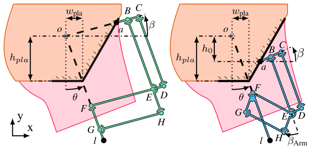
The main limitation of this mechanism is that it protrudes largely away from the volume of a biological thigh. A key reason explaining this encumbrance is the location of the main fixation point a, that must be near the top of the rigid plate. Indeed, the absolute orientation of this segment – defined as the angle $\beta$, see Figure 3 – cannot be decreased too much if the device has to reach an angular position $\theta$ of about 90° when sitting down. For $\beta$ $\leq$ 0°, the mechanism would indeed reach a singular configuration over its movement range. This must be avoided since no torque could be delivered through the prosthesis in such a singular configuration. For the same reason, the more the parallelograms are folded, the more the internal stresses rise in their joints. Taking $\beta$>0° and large enough reduces this constraint that will directly impact the structure dimensioning. Similarly, reducing the distance BC degenerates the parallelogram in a way that internal stresses will rise; and reducing the distance aB is limited by the physical space required for the connection and the assembly.
A modified version of the double parallelogram mechanism is proposed with a tilted double parallelogram, also depicted in Figure 3 (blue). It starts by considering a lower attachment point a as a hard constraint, in order to decrease the mechanism encumbrance. The vertical distance between the center of motion o and this attachment point a is defined by the parameter $h_0$. Importantly, the virtual shape defined by oBEF must keep the shape of a parallelogram, otherwise F will not rotate about o. This is achieved by tilting the second parallelogram in such a way that EF is parallel (and of equal length) to oB. The offset angle $\beta_\text{arm}$ between BE and EH is a free parameter that must be tuned such that the parallelogram EFGH never reaches a singular configuration across its movement range. As such, F, l, and o belong to the same line, such that the kinematics of the attachment point of the knee module l is similar to the straight implementation previously presented.
Robotran was used to simulate this mechanism to:
A motor and a transmission to actuate the tilted double parallelogram mechanism is designed. Integrating a gearbox in the volume of the prosthesis is not considered as a favorable option since it would greatly increase the device mass.
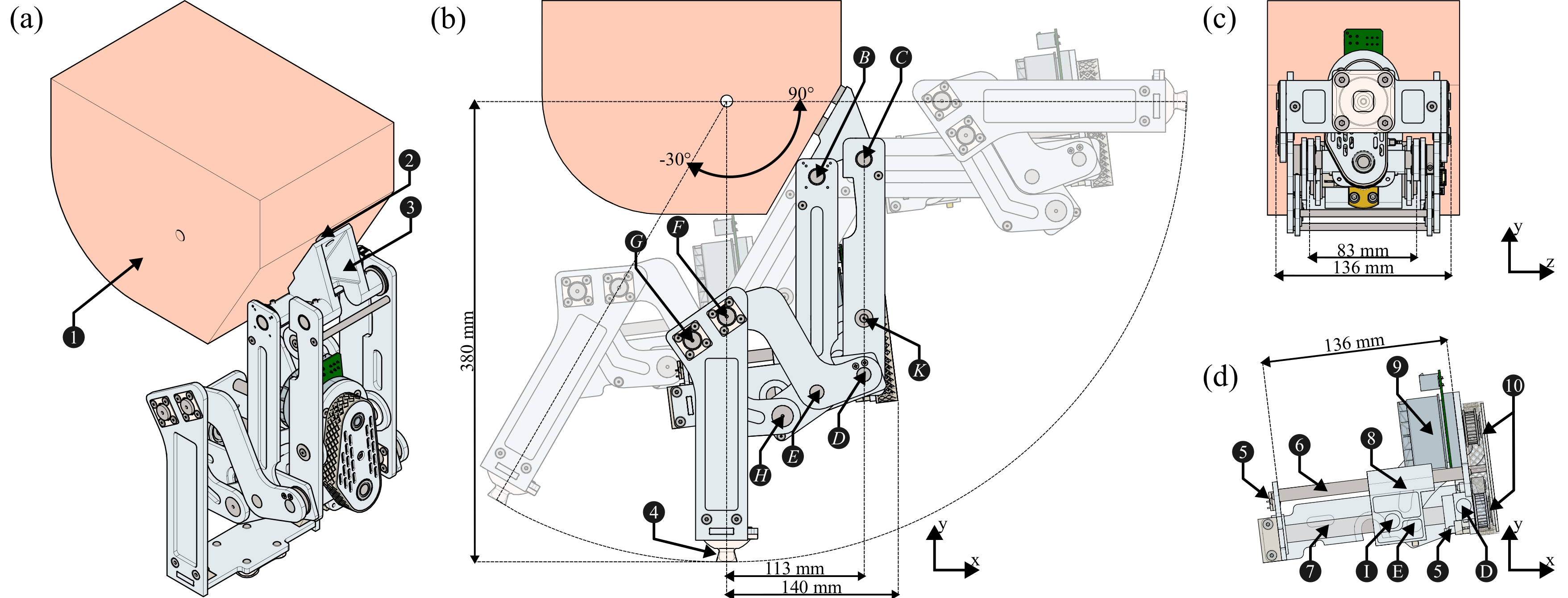
As an alternative, we decided to implement a transmission with a powerscrew directly actuating one of the device segments (Figure 3, left). A motor is attached to the part DEF and is coupled to the powerscrew via a belt. This powerscrew translates (x) a carriage which is connected to the bar CD with two extra joints, denoted I and K, and a connecting rod. Moving the carriage will change the length ID of the triangle IDK and therefore its angles, and eventually the angle of the prosthesis $\theta$.
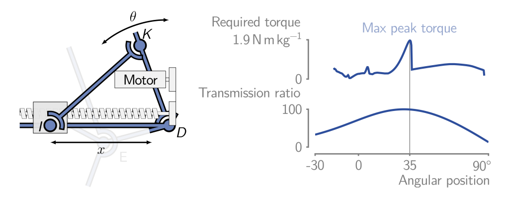
This actuator was added in the Robotran model to compute the torque and optimize the total weight of the mechanism.
Some simulations of the mechanism are available:
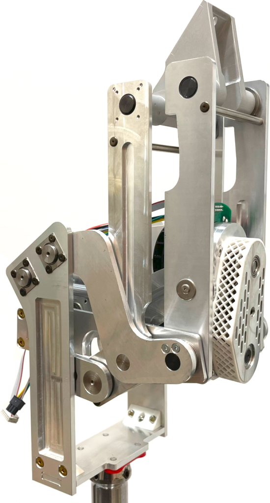
Based on all those simulations, a prototype was designed and assembled (Figure 4).
Devillez, Louis; Herman, Benoît; Ronsse, Renaud. Design of a compact active hip prosthesis with human-like range of motion and torque. 2024 10th IEEE International Conference on Biomedical Robotics and Biomechatronics (Biorob) (Heidelberg, du 01/09/2024 au 04/09/2024).